DESCRIPTION
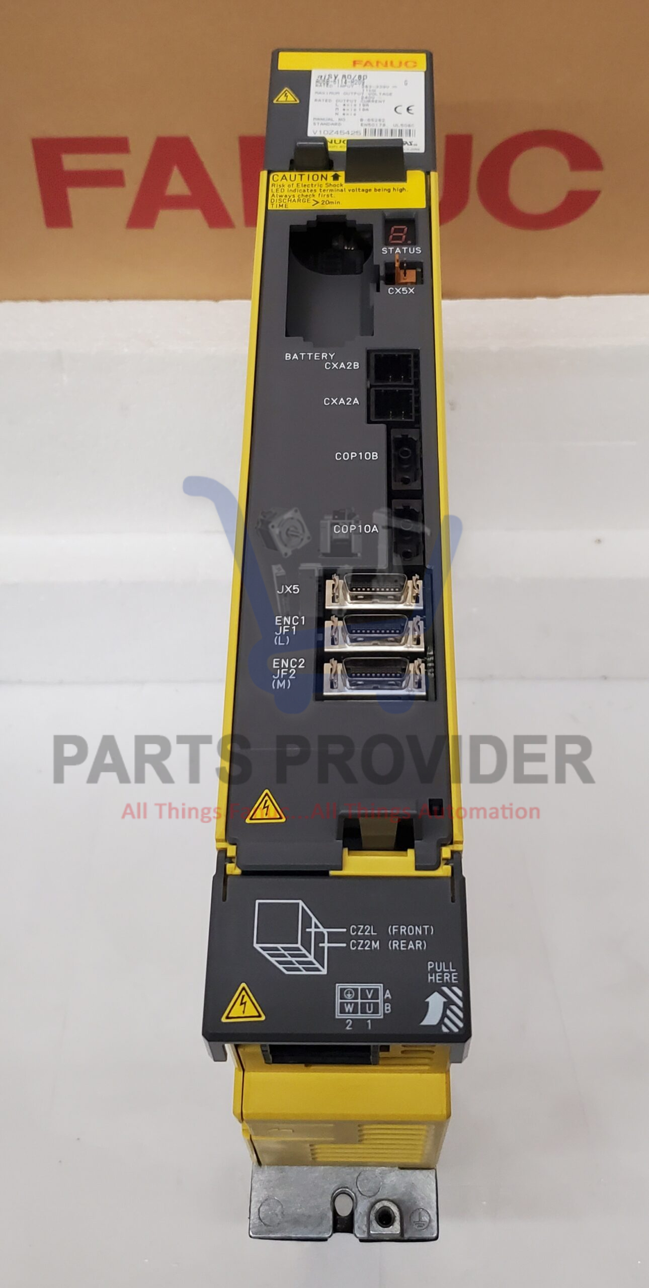
Part Number: A06B-6114-H209
Description: 2 AXIS ALPHA i SERVO MODULE MDL SVM2-80/80i
Product Series: A06B-6114
Control Series: FSi0-A/B, FSi15-A, FSi16/18/20/21-B, PowerMate i
Rated Input: 283-339V, 11 kW
Max Output Voltage: 240V
Rated Output Current: L axis 19 A
M axis 19 A
Manual No. B-65282
Standard EN50178, UL508C
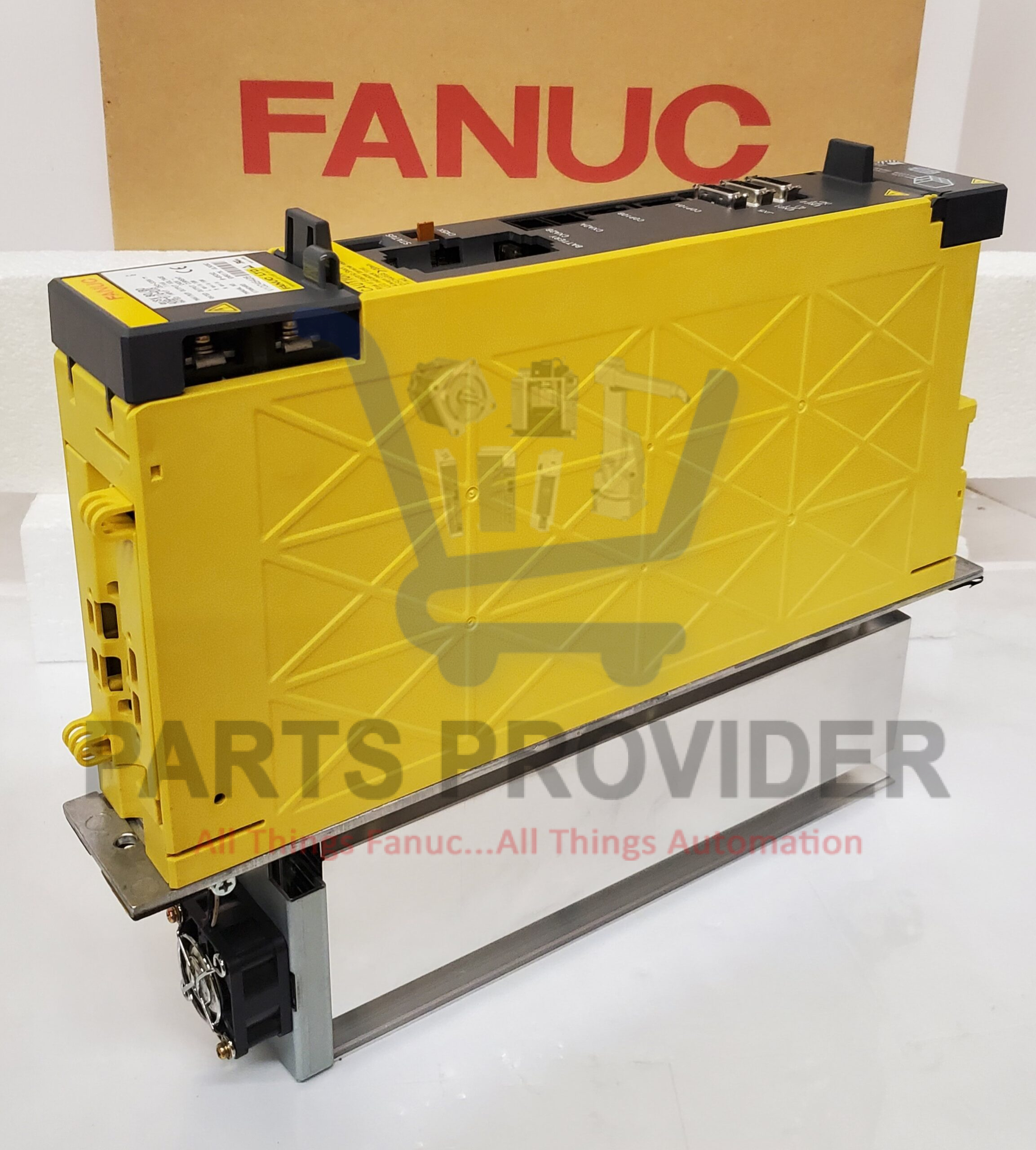
The servo amplifier module (SVM) is used to drive servo motors.
An SVM is selected according to the servo motor(s) connected to the SVM.
There are two types of servo amplifier module, as follows:
<1> Servo amplifier module (SVM)
This module drives a servo motor of the 200-V input series.
Modules for one axis, two axes, and three axes are available.
<2> Servo amplifier module (SVM-HV)
This module drives a servo motor of the 400-V input series.
Modules for one axis and two axes are available.
SVM x – x / x / x HV i
(A) (B) (C) (D) (E) (F)
(A) Model name: SVM = Servo amplifier module
(B) Number of axes: 1 = One-axis amplifier, 2 = Two-axis amplifier, 3 = Three-axis amplifier
(C) L-axis maximum output current value [Apeak]
(D) M-axis maximum output current value [Apeak]
(E) N-axis maximum output current value [Apeak]
(F) For an amplifier supporting 400-V input, “HV” is added.
The servo amplifier αi series employs a modular structure, and is thinner, conserves more space, outputs less heat, and saves more energy than the conventional servo amplifier α series.
Compact
(1) By employing a leading-edge low-loss power device and newly
developed high-efficient heat sink, the fin depth is reduced to 100 mm for all models to decrease the depth of the amplifier by
about 10%.
(2) The amplifier width of boundary models is reduced to the width of models one rank lower. This improvement, together with a
reduction in depth, has decreased the mounting space required in the cabinet by about 30% on the average.
(3) The shape of the cable connector is improved to reduce the length of cable projection into the control board.
(4) From the α(HV)i series, the capacitor module is removed to reduce the installation area.
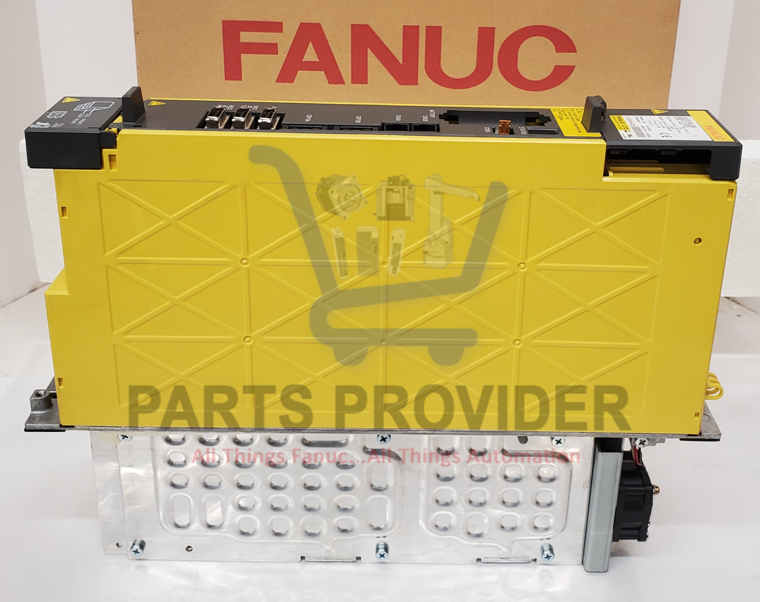
Reduction in cabling
(1) Only one cable is now used for connection between modules.
(2) The connection from the motor output terminal block to the flange section is made internally to eliminate an external
connection via a cable. (A connection from the top of the flange to the system ground on the control board is required.)
Connector attachment to power lines
(1) Connectors are attached to input power lines and motor power lines. (For the large-capacity models, terminal blocks are used.)
The time required for power line attachment to and detachment from the servo amplifier cabinet is substantially reduced.
Improved maintainability
(1) A fan motor can now be replaced in an instant manner, so that the time required to replace a fan motor is reduced substantially.
(2) Connectors are attached to input power lines and motor power lines, so that the time required for servo amplifier replacement is
reduced substantially.
(3) The need to perform reference position return operation after servo amplifier replacement is eliminated.
The servo amplifier αi series has a built-in backup capacitor in the Absolute Pulsecoder as standard. The capacitor enables
absolute position detection operation for about 10 minutes, so that reference position return operation after servo amplifier or
feedback cable replacement is unnecessary.
